Making a wooden gear clock
About 6 months ago I was scrolling through Amazon (we all know how dangerous that is) when I came across the book “Making wooden gear clocks” and I was intrigued. I clicked the buy it now box and 2 days later the book arrived. After skimming through it, I decided that I liked the Genesis clock and that was the clock that I would build. Timing wasn’t right for starting a clock build so I put it on my “to be built one day” list. Fast forward to a few weeks ago. I dusted off the book and started looking through the drawings and decided it was time.
No scroll saw, no problem
This book was put together by the publishers of Scrollsaw Woodworking and Crafts magazine . The book features full size print outs of each part and is meant to be photocopied and then glued to the blanks to give you patterns to cut off of. Pretty cool. Unfortunately I don’t have a scroll saw. I do, however, have a CNC. How do I have a CNC and not a scroll saw? I’m not sure, but it is what it is. One would think that it would be simple to cut everything out with the CNC. In reality, it is. However, I found that the hard part is drawing the pieces to be cut.
Re-drawing the drawings
I laid out the plans on my kitchen table and got out a set of digital calipers, an engineers rule, my computer, and most importantly a set of magnifying glasses with a built in LED light. These drawings were not meant to be easily redrawn. There are no measurements to go from and setting all of the teeth on the gears to be exact to the plans was painstaking at best. I put in about 30-40 minutes a day each morning before work and then a good 2 hours on Saturday and another 2 hours on Sunday mornings. I did this for about 3 weeks before I was done with the drawings. The humor in this is that if I had a scroll saw, I would have been done cutting out parts by now.

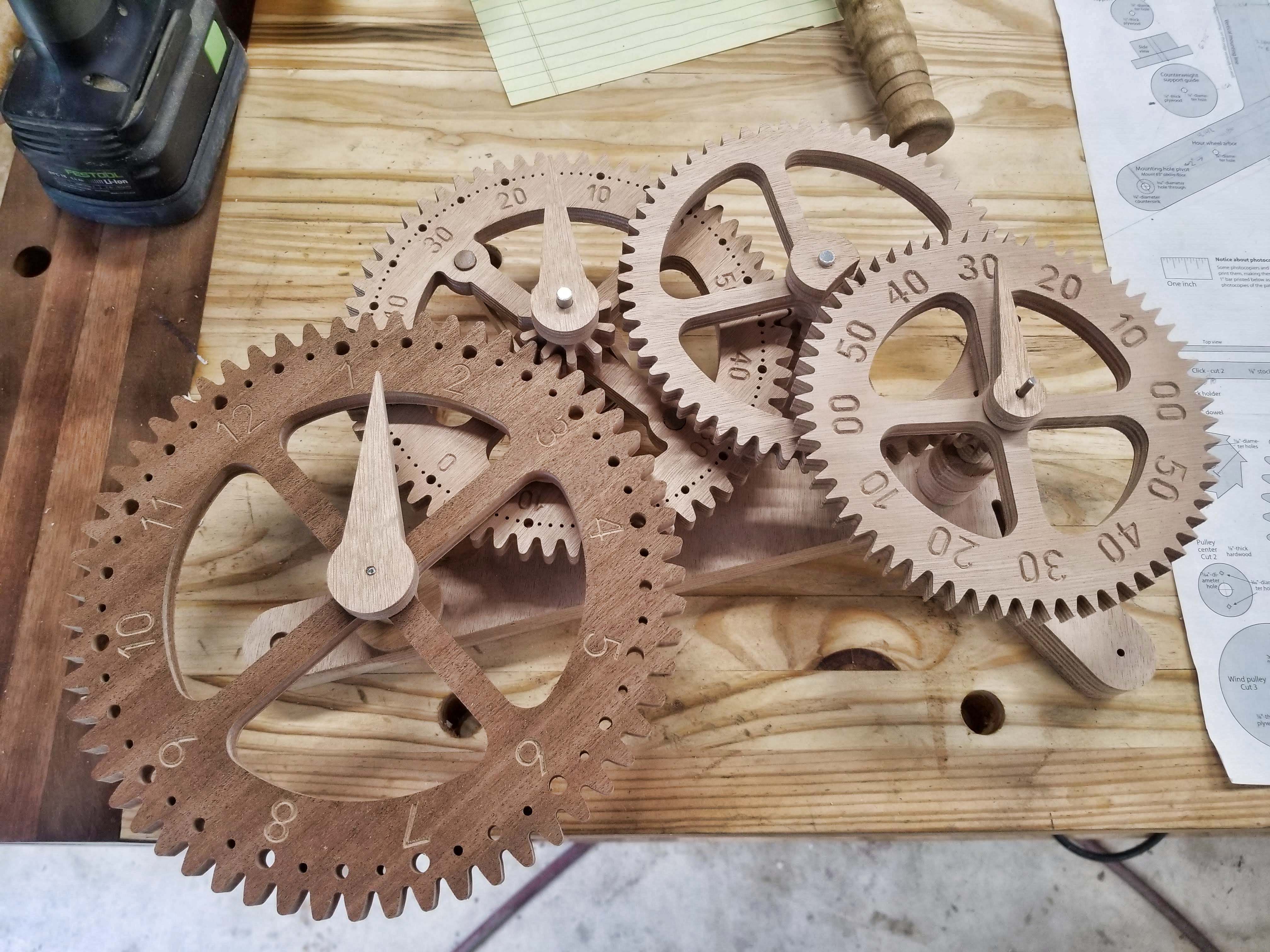
Cutting out the parts on the CNC
Now for the fun part – making sawdust. Or rather, watching the CNC make sawdust. I went through my offcuts pile of plywood and found pieces that would work. I then drew the shape of those pieces in the software and then arranged my parts to be cut within the shape of the plywood. Some of the plywood cuts were triangles, ovals, etc. Since I didn’t come across any 3/8 plywood for all of the gears and pinions, I used 1/2″ instead. I should be able to make it work but I’d likely have to tweak a few things at assembly time. The first piece cut out was the frame out of 1″ okoume plywood. The shape matched up to the pattern so I’m off to a good start. Next up the CNC cut out the hour wheel from 1/2″ sapele plywood. The hour wheel also matched up to the pattern. Nice! I repeated this process until all of the CNC parts were cut out.


Making the clicks
Next up was to make the clicks. The clicks transfer the load from the hanging weights to the gears. I turned the 3/8″ dowel on the lathe from a chunk of walnut. After cutting them to length, I set up the crosscut sled and cut the dado into the ends. After that, I cut the flat inserts that go between the click dowels and the click gears. I made these from cherry and cut them just a hair heavy for thickness on the tablesaw. Using a card scraper, I was able to achieve the final fit by removing just a little bit of material at a time until the pieces fit together tight. I then glued both pieces of the clicks together.

Shafts and dry fit
The last item to make before dry fitting was the shafts. The plans called for 1/8″ and 1/4″ brass rod. I had 1/4″ aluminum and 1/8″ steel rod on hand. As I had used thicker plywood in areas, I cut all of the shafts were cut oversized as I wasn’t sure of the final dimension needed. Once cut, I inserted them into the frame and went back to the plans to see how the supports, spacers, pinions, and gears went on. One by one I placed the pieces on the shafts. Everything lined up and engaged the adjoining gears as they should. Amazing! I’ll call that good for today.

Part 2 blog post coming soon
Part two of the blog is coming soon! In part 2 I show balancing the gears, turning the weight, making a threaded dowel, and gluing up the gears, pinions, and connectors.
Comments are closed