To see the start of making a wooden gear clock, check out part 1 found here. In part 1 I talk about the plans, initial layouts, and cutting the pieces to size. At the end of part 1 all of the gears and pinions are cut out and are dry fit. Time to make the other pieces of the assembly.

A view of the underside of the wooden gears after being dry fit for the first time
The pendulum assembly
The pendulum assembly is made up from a handful of components. There’s the pallet which contacts the seconds gear, the shaft, and then the adjustable weighted assembly at the bottom. I used a piece of cherry for the shaft. The plans called for 3/8 dowel but I preferred the look of a square rod so I made a square shaft from cherry and then rounded over the last 1″ to allow it to fit into the hole I had bored in the bottom of the pallet. The bottom was drilled and tapped to accept the threaded rod.
You can purchase threaded rod from most hardware stores, however, I had some steel dowel and a tap set so I decided to make my own. I used my drill press to hold the rod which allowed me to use the table of the drill press to ensure I was cutting square threads. I made the threaded rod slightly longer than the plans. Last to do was to fill the pendulum with weights and close it up. Plans called for BBs, of which I was in short supply, so I used short drywall screws. I then glued the skins to the front and back of the pendulum.

A view of the guts of the pendulum before adding weight and closing it up.

Making my own all-thread rod for the pendulum
Balancing the gear wheels
Next up was balancing the gear wheels. I mounted a shaft in the side of my vice and made sure the shaft was sitting level. I then mounted the wheels one by one and checked to see if there were any heavy spots. Heavy spots are indicated by the wheel turning on its own. If it turns on its own, the heavy spot is at the bottom when it comes to rest. I would then bore out a small hole on the back side of the gear to remove some of the weight and check again. Once it was good, I’d turn the gear 90 degrees and check for movement again. Then I’d turn it 90 degrees two more times to check all areas for even subtle movement before calling the gear good.
You can see the hour wheel pictured here was way out of balance. I had to remove a lot of weight to get it to balance out. Please note that it looks like a few of the smaller holes around the outside edge of the wheel are missing, however, they were bored but didn’t break through the veneer on this side. A quick sand took care of that.

Balancing the hour wheel. This wheel was bad!
The drive weights
The last items to build are the weights and counterweights. The plans call for around 6 pounds of weights to drive the clock. It also called for a large diameter piece of copper tubing that would be filled with lead shot to give the approximate weight. I didn’t have the tubing but I did find a few pieces of other tubing laying around. For each piece of tubing I turned a pair of finials on the lathe with a tenon that was a snug fit inside of the tubes. I then epoxied one side of the finial to the tube, filled it with lead shot, and then epoxied the other side in place. Once the epoxy set up, I added eye hooks to the top of each finial for hanging the weights.
Lastly, I built a cradle to hang the weights from the line that drives the clock. I offset the mounting hole on the top of the cradle to get the cradle to sit level with two different weight weights.

Final sanding of one of the drive weights on the lathe.

The final drive weight assembly.
The counterweight
The counterweight was a piece of cherry that I turned on the lathe to match the finials on the weights. Once turned and sanded, I added an eye hook to the top and gave it a light coat of oil and it was ready for service.

Turning the cherry counterweight on the lathe.

The cherry counterweight.
Installation
Everything is ready. Time to install it. I had a location in the house already picked out so I took it in and laid it out. The first screw is on the left hand side of the unit and it is the pivot point for the clock assembly. The second screw was on the right side and there was an adjustment slot in the frame that allows you to pivot the clock up or down. Based on the plan recommendations, I plumbed up the legs on the top of the frame with a level and then I set the right screw in the center of the adjustment slot. I got the weights and counterweights hung, the pallet and pendulum mounted, and all of the gears in place.

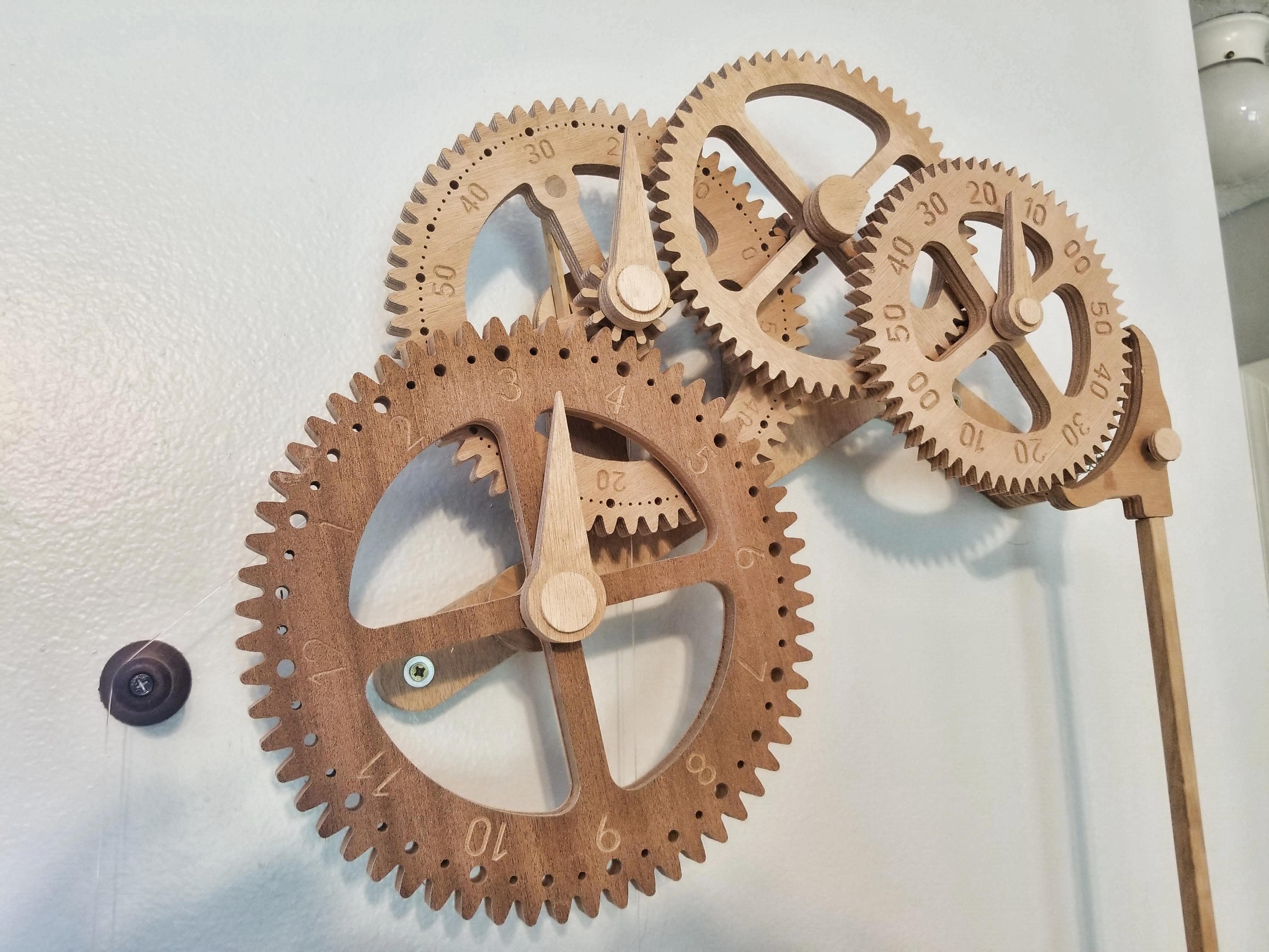
The wooden gear clock assembled and ticking.
Some minor adjustments
I gave the pendulum a slight push and let it go. Tic-toc-ti…..and it bound up. I adjusted the right side of the clock up to get the pendulum to run properly. I needed a little more adjustment that was in the slot so I ended up relocating the right side mounting screw up to get it just right. It surprised me to see that the clock was so picky – I had to have the height on the right side within 1/32″ of the sweet spot for it to run true. I gave the pallet and gears a light hit of beeswax to help lubricate everything. That helped smooth things out.
The clock was still binding up on occasion so I hung a water bottle from the weights. No more binding. The plans called for around 6 pounds of weights and with my set up I was closer to 5. I needed a little bit of extra weight so I found a 32 ounce fishing weight I had laying around and mounted that in the center. Maybe one day I’ll make a nice third weight there.
Final tweaks
At initial onset, the clock was running slow. The plans called for letting the clock run for a few days before making any adjustments as sometimes they will slow down or speed up. After letting it run for about a week, the clock was consistently running about 3 minutes slow in 12 hours. Over the next few days I adjusted the pendulum up on the threaded rod to the maximum amount of play. Still running slow. I trimmed a bit off of the bottom of the pendulum shaft and started re-adjusting. This time I was able to dial in beat of the pendulum to be within a few seconds over 24 hours. That’s extremely impressive.
What would I change?
If I were to build this clock again, what would I do different?
- The weights. What I made is beautiful, however, at 28″ from the bottom of the weight to the top of the cradle, I lose a lot of potential drive hours. I’d try and do a shorter, fatter weight that’s less than 12″ tall. The 16″ difference should yield an extra 3 hours or more of time keeping before needing reset.
- Painted numbers. I found the numbers hard to read so I ended up painting the hour numbers. The numbers were engraved, which looks great, except they were impossible to read from any distance away. So I painted the numbers a contrasting color (white) which really made them pop. I plan to do this for the hour and second hands also.
- Longer threaded rod. The threaded rod on the pendulum was made slightly longer than spec, however, I’d to even longer. I didn’t want to use a metal nut on the bottom of the pendulum so I turned a piece of walnut and drilled and tapped the hole. Wood is softer than metal so needs more thread contact to get a good purchase without stripping. I’d add an extra inch, maybe inch and a half to the threaded rod.
- Solid wood hour hands. I’d pick a contrasting color wood for the hour hands. Also, I’d not bore them completely through. They way they’re drawn has the shaft bored completely through and then there’s a secondary cap to hide that hole. I’d simplify that and stick with just a simple piece of hardwood.
- Enlarge the adjustment slot. Based on having to relocate the right hand adjustment screw when mounting the clock, I’d enlarge the slot and nearby frame to allow for a bit more play.
Comments are closed